

Transform sensor data
Calibrate a vibrating wire piezometer
Configure a vibrating-wire conversion chain from frequency to pressure using sensor-specific coefficients.
The process follows a consistent conversion chain regardless of sensor manufacturer:
Understanding the conversion chain
Section titled “Understanding the conversion chain”VW piezometers output a raw frequency reading in Hz. This cannot be used directly for pressure calculation. The conversion happens in two stages.
Stage 1 - Hz to Digits
The raw Hz reading is first converted to a digits value:
Digits = Hz² / 1000Digits are directly proportional to the applied pressure, making them the correct unit for applying calibration factors.
Stage 2 - Digits to kPa
The digits value is then converted to kPa using the linear formula:
Pressure (kPa) = k x (Current Digits - R0)Where:
| Variable | Description |
|---|---|
| k | Linear calibration factor in kPa per digit, from the sensor calibration sheet |
| Current Digits | The live digits reading calculated in Stage 1 |
| R0 | The digits reading taken at installation under zero pressure conditions |
These two stages form the core of every VW piezometer calibration in Orion Data.
Temperature correction
Section titled “Temperature correction”Most VW piezometers also include a thermistor. A temperature correction can be applied to improve accuracy where the sensor is subject to temperature variation:
Temperature Correction = CT x (Current Temperature - T0)The correction is added to the Stage 2 pressure result:
Final Pressure (kPa) = [k x (Current Digits - R0)] + [CT x (Current Temp - T0)]Where:
| Variable | Description |
|---|---|
| T0 | Temperature at the time of the zero reading, in degrees Celsius |
| CT | Temperature coefficient in kPa per degree Celsius, from the calibration sheet |
Temperature correction is optional. Where the sensor is sealed in a borehole or buried in fill, temperature variation is typically small and correction may not be necessary.
Calibration coefficients by manufacturer
Section titled “Calibration coefficients by manufacturer”All supported manufacturers use the same formula. The only differences are how the coefficients are labelled on their calibration sheets.
| Manufacturer | k label | R0 label | CT label |
|---|---|---|---|
| Geosense | k | R0 | CT |
| HMA Geotechnical | CP | F0 | CT |
| Geokon | G (gauge factor) | R0 | K (thermal factor) |
| RST Instruments | CF | F0 | CT |
Always source these values from the calibration sheet supplied with the individual sensor. Each sensor has unique coefficients.
Building the calibration in Orion Data
Section titled “Building the calibration in Orion Data”The steps below build the full Hz > Digits > kPa conversion chain with temperature correction in the Calibration Step Groups editor.
Before you begin
Section titled “Before you begin”Locate the sensor calibration sheet and note the following values:
- R0 - zero pressure digits reading taken at installation on site
- k - linear calibration factor (kPa per digit)
- T0 - zero temperature reading taken at installation (degrees Celsius)
- CT - temperature correction factor (kPa per degree Celsius)
{ The site zero reading must be used for R0 and T0. Do not use the factory zero reading unless no site zero was recorded. }
Navigate to the calibration editor
Section titled “Navigate to the calibration editor”- Navigate to Devices and select the relevant device.
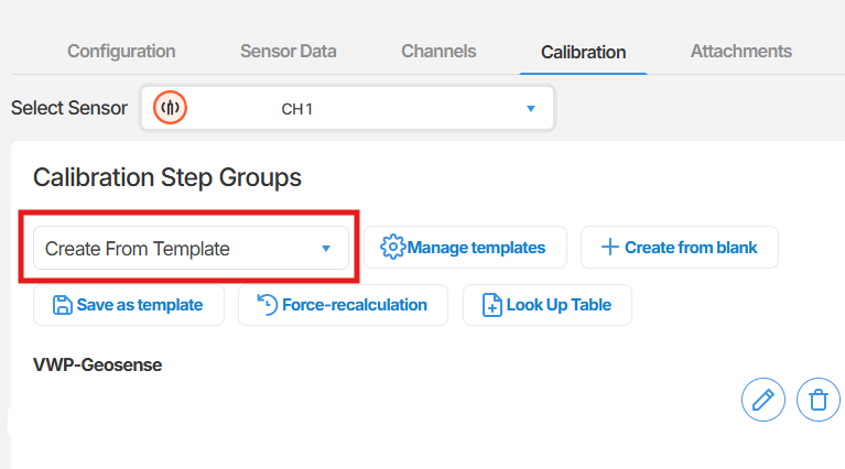
- Select the Calibration tab.
- Select the sensor channel to calibrate from the Select Sensor dropdown.
- Enter a descriptive name in the Group Name field, for example VWP-Geosense or VWP-HMA.
Stage 1 - Hz to Digits
Section titled “Stage 1 - Hz to Digits”The raw sensor channel outputs in Hz. Steps 1 and 2 convert this to digits.
Step 1 - Square the Hz reading
- and: Sensor value - select This Device, choose the VW sensor channel
- then: multiply ( * ) - Sensor value - select This Device, same channel
This multiplies the Hz reading by itself (Hz x Hz = Hz²).
[Attach Image 1 - showing Step 1: Sensor value x Sensor value from This Device, Group Name VWP-Geosense visible]
Step 2 - Divide by 1000
- and: Previous step value - select step 1
- then: divide ( / ) - Value - Non-constant - enter 1000
The result of step 2 is the digits value (Hz² / 1000).
Stage 2 - Digits to kPa
Section titled “Stage 2 - Digits to kPa”Steps 3 and 4 apply the linear calibration formula to convert digits to kPa.
Step 3 - Subtract the zero reading (R0)
- and: Previous step value - select step 2
- then: subtract ( - ) - Value - Non-constant - enter the R0 value from the calibration sheet
Step 4 - Multiply by the calibration factor (k)
- and: Previous step value - select step 3
- then: multiply ( * ) - Value - Non-constant - enter the k value from the calibration sheet
The result of step 4 is the pressure in kPa. For many applications, this is sufficient and steps 5 to 7 are not required.
Temperature correction (optional)
Section titled “Temperature correction (optional)”If temperature correction is required, add steps 5 to 7 to apply the CT factor and add it to the kPa result from step 4.
Step 5 - Calculate temperature change
- and: Sensor value - select This Device, choose the temperature channel
- then: subtract ( - ) - Value - Non-constant - enter the T0 value from the calibration sheet
Step 6 - Apply the temperature correction factor (CT)
- and: Previous step value - select step 5
- then: multiply ( * ) - Value - Non-constant - enter the CT value from the calibration sheet
Step 7 - Add temperature correction to pressure
- and: Previous step value - select step 4
- then: add ( + ) - Previous step value - select step 6
The result of step 7 is the final temperature-corrected pressure in kPa.
Constant vs Non-constant values
Section titled “Constant vs Non-constant values”When entering any coefficient value (R0, k, T0, CT), always select Non-constant. This stores the value as a fixed number specific to that sensor.
Constant is used only when the input value is drawn from another live sensor channel rather than a fixed number.
Polynomial calibration (Geokon)
Section titled “Polynomial calibration (Geokon)”For Geokon sensors requiring higher accuracy, the calibration sheet provides second-order polynomial coefficients A and B alongside R0. The polynomial formula is:
Pressure (kPa) = A x (Reading)² + B x (Reading) + CWhere C is calculated from the calibration sheet zero data. If you need to configure a polynomial calibration for a Geokon sensor, contact EWS Monitoring for assistance as the step configuration differs from the standard chain above.
Summary
Section titled “Summary”All VW piezometers follow the same two-stage conversion: Hz is first squared and divided by 1000 to produce a digits value, then the digits value is converted to kPa by subtracting the zero reading and multiplying by the calibration factor. An optional temperature correction can be added as additional steps. All coefficient values are sourced from the calibration sheet supplied with each individual sensor.
Next Steps
Section titled “Next Steps”- Locate the calibration sheet for each sensor before beginning configuration
- Record the site zero reading at the time of installation before applying the calibration
- Verify the output is reading expected pressure values once the calibration is saved
- Contact EWS Monitoring if polynomial calibration is required for Geokon sensors